
The insulation monitoring device is connected between the live supply conductors and earth and superimposes a measuring voltage Um. In the event of an insulation fault, the insulation fault RF closes the measuring circuit between the system and earth, generating a measuring current Im that is proportional to the insulation fault. This measuring current generates a corresponding voltage drop at the measuring resistance Rm, which is evaluated by the electronics.
If this voltage drop exceeds a specific value equivalent to the under shooting of a specific insulation resistance, a signal will be output. IEC 61557-8 specifies detailed requirements to be met by insulation monitoring devices. Insulation monitoring devices serve as early-warning systems, providing operators with the information they need in order to have appropriate maintenance measures taken in good time.
IEC 61557-8 specifies that insulation monitoring devices must support a prescribed measuring principle which enables them to monitor both symmetrical and asymmetrical deteriorations in insulation.
Notes:
Symmetrical insulation faults are common in DC voltage systems and control circuits. If the resistance of both insulation faults is approximately equal, insulation monitoring devices ope-rating on the basis of the principle of superimposed voltage measurement will not be able to detect these insulation faults. It is for this reason that IEC 61557-8 requires the use of continuous insulation monitoring devices.
A popular measuring method is to superimpose a measuring DC voltage between the phase and PE conductor.
This measurement procedure is suitable for monitoring conventional AC, 3(N)AC systems, e.g. motors. If it is used in AC, 3(N)AC systems containing galvanically connected DC components, these DC currents will distort the measurement result. In other words, insulation faults on the DC side will be signalled with an increased response sensitivity.
The system leakage capacitances Ce prevailing in the system are simply charged to the measuring voltage and have no effect on the measurement following a brief initial response.
The AMP measurement method patented for Bender is based on a special clocked measuring voltage which is controlled by a micro-controller and adapts automatically to the prevailing system con-ditions. Software-based evaluation enables system leakage currents causing interference on the evaluation circuit to be differentiated from the measured variable proportionate to the insulation resistance in ohms. This means that broadband interferences as they occur, for example, during converter operation, do not adversely affect the precise determination of the insulation resistance.
The AMP Plus measurement method takes interference suppression to the next level. Devices supporting this measurement method can be used universally in AC, DC and AC/DC systems, e.g. systems with varying voltages or frequencies, high system leakage capacitances or DC voltage components. This makes them ideal for use in today's state-of-the-art distribution systems, which are usually subject to this type of interference (converters, EMC).

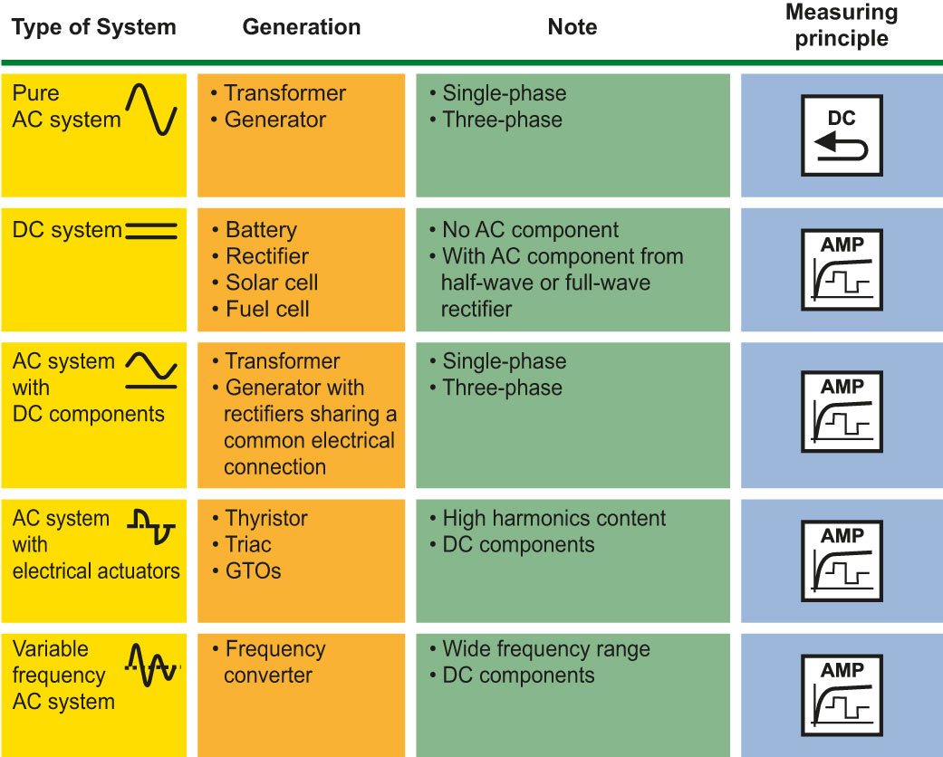
There is a direct relationship between the IT system, its structure, its components and the measurement method of the insulation monitoring device. Knowing which insulation monitoring device works with which measurement method is therefore important from a planning point of view. The following table lists the measurement methods that can be selected on the basis of system parameters.
